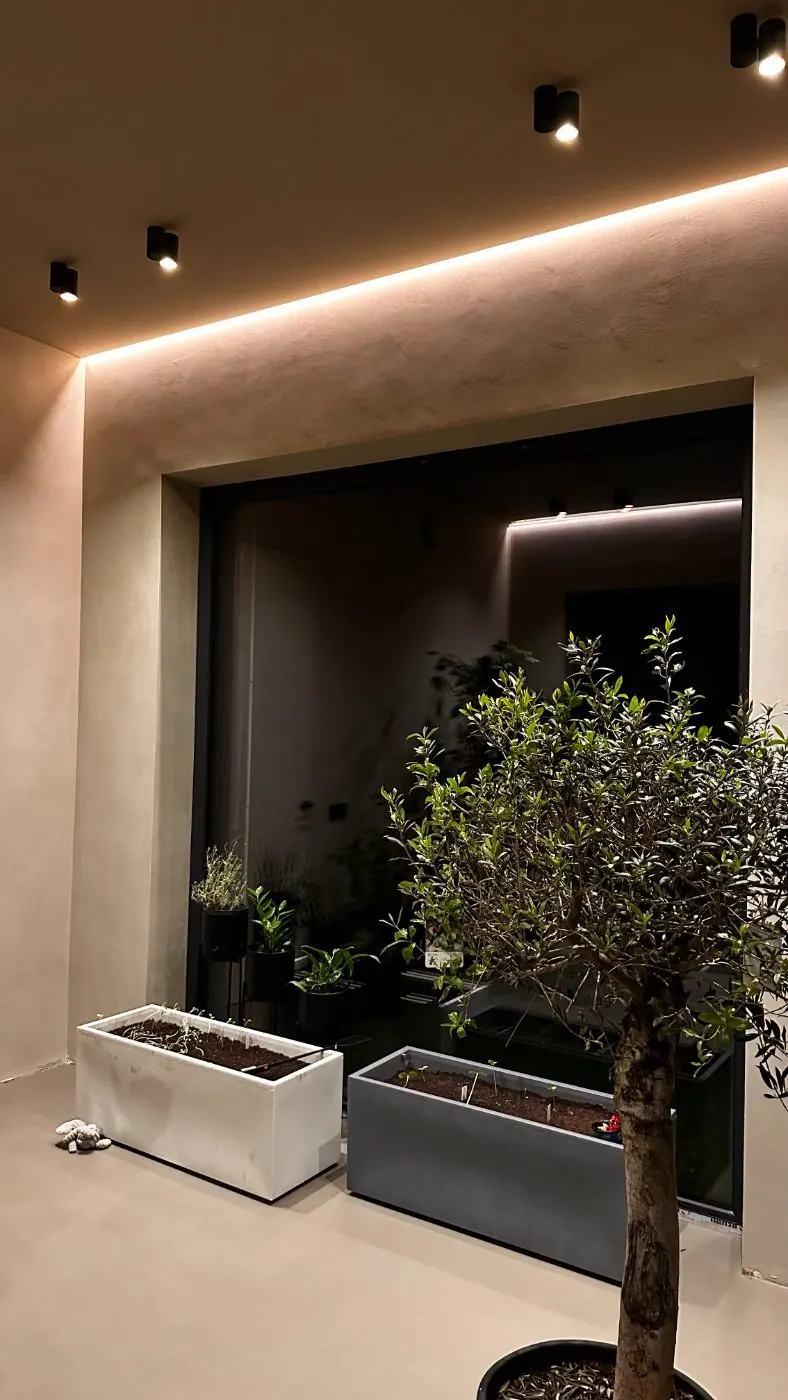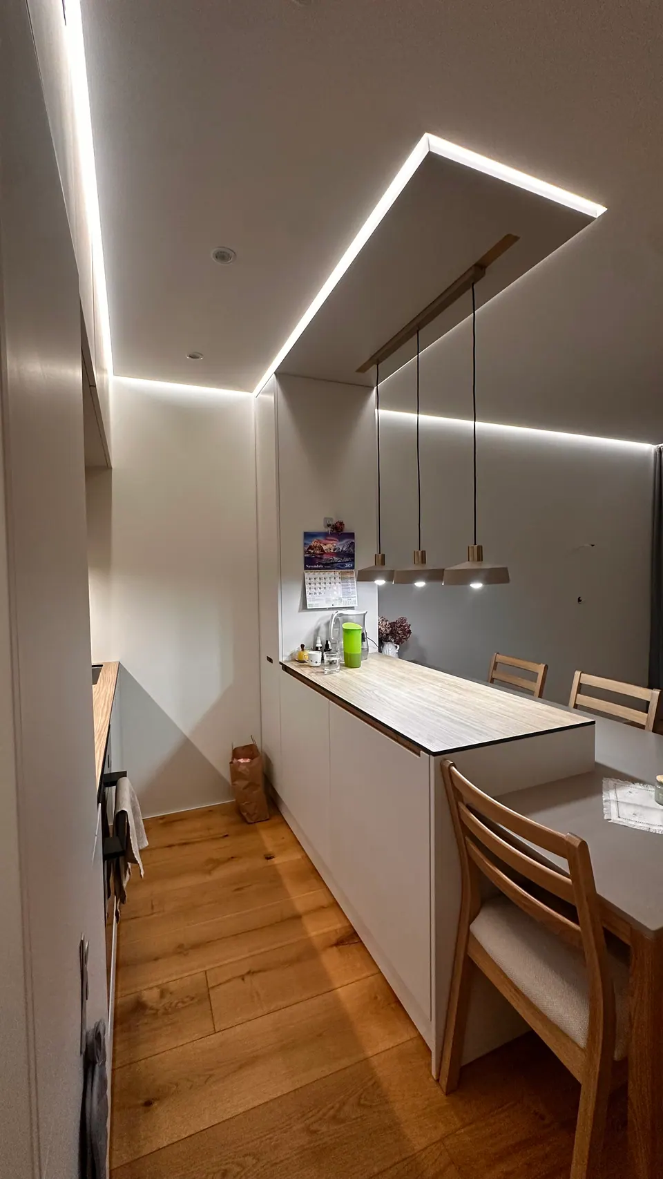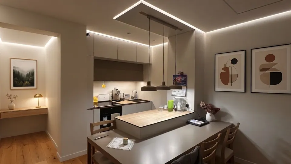
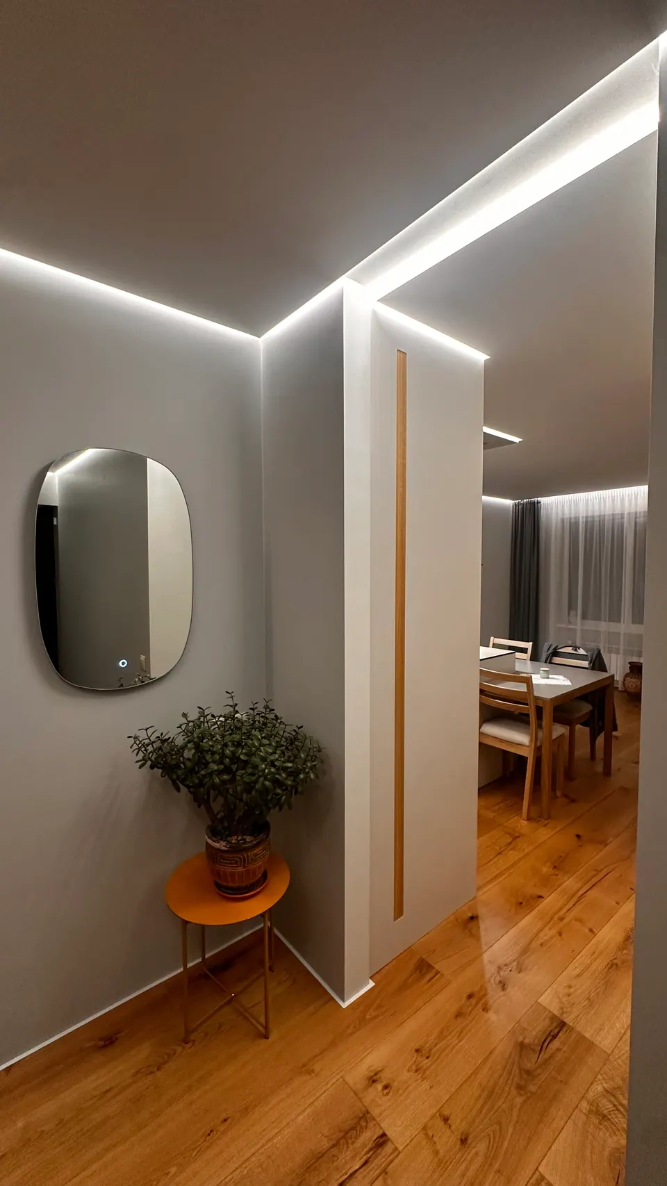
A shadow gap detail specification should name the exact profile (product code and family), the visible reveal dimension, the finish or RAL code, the standard length and joint positions, any LED components, the accessories, and the set-out line and level. Show every run on the plans and every junction type in a large-scale section, so the contractor can order the right profile before the plasterboard goes up.
A note that only says “shadow gap” leaves the contractor to choose the profile, the finish and the detail. The rest of this article covers what to state, where it belongs in the drawing set, and example wording.
What the specification should state
| Item | What to state | Where to find it |
|---|---|---|
| Profile | Product code and name, for example AST35 Ceiling LED Shadow Gap Profile | Product page |
| Reveal size | Visible width or height of the reveal | Product page, dimensioned drawing where available |
| Finish | Mill, silver, black, white or RAL code | Product page; RAL on request |
| Length | Standard length (2500, 2600 or 3000 mm, depending on the profile) and joint positions | Product page, plans |
| LED | Diffuser product code; LED strip and driver by the lighting or electrical designer | Product page lists compatible diffusers |
| Accessories | Corners, connectors, end caps or accessory sets | Product page |
| Set-out | Line, level and the reference surface (finished, not bare board) | Plans and sections |
| Interfaces | Doors, windows, curtain tracks, tiles, access panels | Coordination drawings |
The finish is easy to leave out and hard to change later, because standard finishes vary by profile. Our guide to choosing a finish shows what each profile family offers.
Where the detail lives in the drawing set
Plans and reflected ceiling plans
Mark every shadow gap run with a tag that refers to the specification. Show where runs start and stop, every internal and external corner, every open end, and planned joint positions. For LED profiles, show the driver positions and access points as well.
Sections
Draw a large-scale section through each junction type: ceiling to wall, wall reveal, wall to floor. Show the framing, the board layers, the profile, the finished surface and, for recessed ceiling profiles, the ceiling void. Most site problems with shadow gaps come from a profile that does not fit the build-up behind it. Our article on plasterboard and profile choice covers what to check.
Elevations
Show where a reveal meets door frames, window reveals, tiled areas or a curtain track. These are the places where the contractor otherwise has to improvise.
Manufacturer drawings
Dimensioned drawings are on the product pages where available. We do not publish DWG or CAD files. Anything else, including installation guidance and build-up sequences, is sent on request through our resources page. We aim to reply within one working day.
Example specification wording
Specific wording leaves less to interpretation. Two examples, using products from our range:
Ceiling to wall junction, lit. Recessed aluminium ceiling LED shadow gap profile AST35, 35 mm, finish white, standard length 2500 mm, plastered in flush with plasterboard in accordance with the manufacturer’s installation guidance. Diffuser: ASL40, matt white. LED strip and driver: to the lighting designer’s specification; driver positions and access as shown on the electrical drawings.
Wall to floor junction, skirting. Surface-mounted aluminium skirting profile ASP60, 60 mm, finish black, standard length 2600 mm, with accessory set F60 (internal corner, external corner, connector, right end, left end) as shown on plan.
Adjust the wording to your specification format, but keep the four fixed points: product code, dimension, finish and the components that complete the run.
LED: what belongs in the profile specification
An LED shadow gap involves three parties: the architect, the lighting or electrical designer and the electrician. Split the specification accordingly.
- Profile and diffuser. Name both. The product pages list which diffuser fits which profile; ASL40, for example, is listed as compatible with AST-35 and RST-40.
- LED strip. Where a product page lists an LED specification for the profile, refer to it. Otherwise the strip is specified by the lighting or electrical designer.
- Driver and access. Show driver positions and access on the drawings. They have to be agreed before boarding, because the driver must stay accessible after the room is finished.
- Electrical work. Must be carried out by a qualified electrician to local regulations.
Sequence on site
The specification should also make the order of work clear, because the profile is installed earlier than a traditional trim:
- Set-out of the profile line and level from the drawings.
- Cabling for LED runs and driver positions, before boarding.
- Profile fixed to the framing, substrate or board, following the installation guide for that profile.
- Perforated flange bedded in jointing compound, taped and skimmed flush with the board.
- Surface finished and painted.
- LED strip and diffuser inserted after decoration.
Common gaps in shadow gap specifications
- No product named. “Shadow gap, 10 mm” without a product code leads to a substitute chosen on price or availability.
- No finish. The finish is decided by whoever places the order.
- LED profile without a diffuser. The channel is installed, the diffuser is missing, and the light line is late.
- Skirting runs without accessories. Corners and ends are mitred or cut on site instead of using the matching components.
- Long runs without joint positions. Joints land in the most visible place.
- Unclear set-out reference. The reveal is set to the bare board and ends up out of line with the finished surface.
If you need a dimensioned drawing or installation guidance for a profile you are specifying, ask us. Contractors and other trade buyers can also request a free sample box to check profile sections and finishes before the specification is final.